Configuring the P201 counter card
This chapter assumes you have have a running a bliss configuration server (beacon) available on your system.
The CT2 card has two models:
- P201: the
PCIversion of the card- 8 input channels
- 2 input/output channels
- C208: the
cPCIversion of the card- 10 input channels
- 2 input/output channels
The C208 has been discontinued and is not supported by bliss.
Warning
BLISS is tested with the 3.3 version of the P201 kernel driver. Any other version may cause troubles.
Architecture
A brief diagram explaining how the P201 is used by bliss:
Driver installation
The driver is available as an external project.
see: CT2 driver project on gitlab
Note
If you are at ESRF you can install it with:
* blissinstaller
* bliss_drivers config
* (need root password, see: https://passdoggo.esrf.fr)
BLISS has to be installed to get bliss-ct2-server script.
The CT2 Bliss RPC server has to run on the PC where the card is installed by typing:
$ bliss-ct2-server
INFO 2017-10-30 15:14:57,680 CardInterface(/dev/ct2_0): connecting to /dev/ct2_0
INFO 2017-10-30 15:14:57,684 CT2Server: Serving CT2 on tcp://0.0.0.0:8909...
Note
If you are at ESRF, use supervisor to start it. example of startup script:
[group:EH1]
programs=P201_zerorpc
priority=100

[program:P201_zerorpc]
command=bash -c ". /users/blissadm/bin/blissenv && exec bliss-ct2-server --address /dev/ct2_0"
priority=800
environment=HOME="/users/blissadm"
user=blissadm
startsecs=2
autostart=true
redirect_stderr=true
stdout_logfile=/var/log/%(program_name)s.log
stdout_logfile_maxbytes=1MB
stdout_logfile_backups=10
stdout_capture_maxbytes=1MB
By default it runs on port 8909. To run with different options type: bliss-ct2-server --help.
Configuration
Minimal configuration example:
plugin: ct2                   # (1)
name: p201_eh1                # (2)
class: CT2                    # (3)
type: P201 ???
address: tcp://lid421:8909    # (4)
(replace the address with the one that makes sense to you)
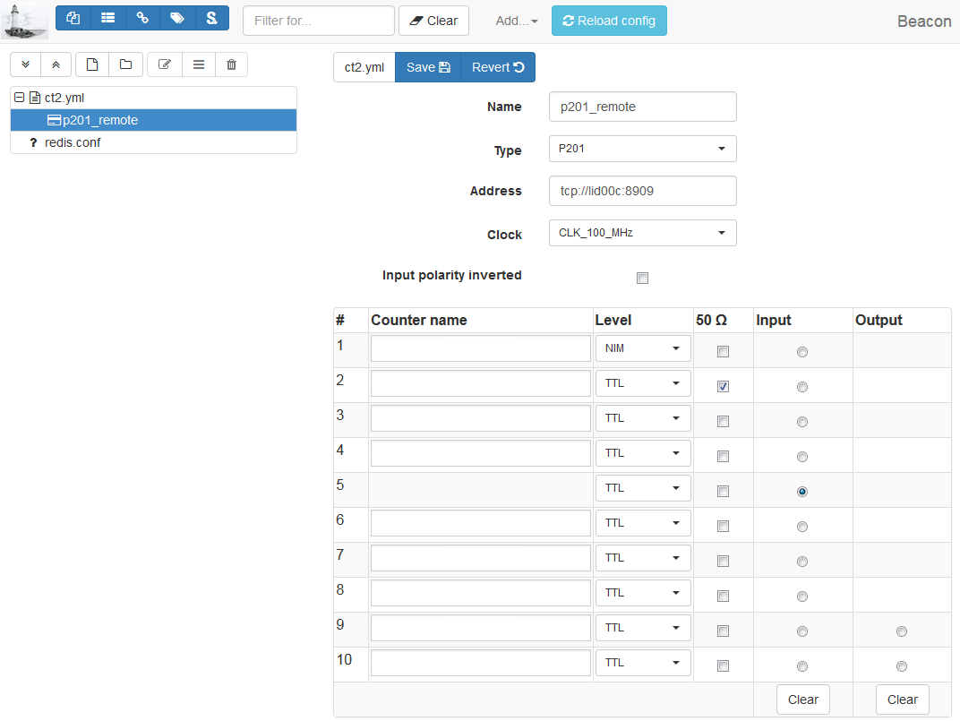
Since the full YAML configuration can be quite complex, we suggest using the the web configuration tool which provides a more user friendly interface:
To use counters in a BLISS session, the P201 object (p201_eh1) has to be added
to the config-objects list.
Attention
The counters corresponding to the channels are not exported.
Here is a more complete example including channel configuration and external trigger/gate:
plugin: ct2                    # (1)
name: p201_eh1                 # (2)
class: CT2                     # (3)
address: tcp://lid312:8909     # (4)
type: P201                     # (5)
clock: CLK_100_MHz             # (6)
external sync:                 # (7)
  input:                       # (8)
    channel: 7                 # (9)
    polarity inverted: False   # (10)
  output:                      # (11)
    channel: 10                # (12)
    mode: gate                 # (13)
channels:                      # (14)
- address: 1                   # (15)
  counter name: pC1            # (16)
  level: NIM                   # (17)
- address: 10
  level: NIM                   # (18)
- plugin name (mandatory:
ct2) - controller name (mandatory)
- plugin class (mandatory)
- card address (mandatory).
tcp://<host>:<port>to connect to a remote bliss rpc CT2 server or/dev/ct_<card_nb>for a local card. - card type (optional, default:
P201). Valid values are:P201(historical: before the C208 was forseen to be supported as well) - card clock (optional, default:
CLK_100_MHz) - External synchronization signal configuration
- Input signal: used for external trigger/gate (optional, default: no input)
- Input signal channel (mandatory if input keyword is given). Valid: [1, 10]
- Interpret input signal polarity inverted (optional, default: False)
- Output signal: used for output gate signal
- Output signal channel (mandatory if ouput keyword is given). Valid: [9, 10]
- Output signal mode (optional, default: gate). Only possible value today is gate
- Channel configuration
- channel address (mandatory). Valid: [1, 10]
- counter name (optional). Needed if want to count on this channel.
- channel input level (optional, default: TTL)
- channel input/output level (optional, default: TTL)
Note
If external sync input/output channel is given, the channel counter name is ignored as this channel cannot be used to count
Note
If a bliss rpc address is set, the type is ignored. In this case it is
specified at the bliss rpc server command line.
Configuring 2 or more independent cards
Sometimes, the 10 channels provided by a single CT2 card are not enough. You may need two or more cards in order to fulfill your needs.
If the acquisition of the CT2 cards is triggered by an external signal, we say that all the CT2 cards are slaves since the control of the acquisition is done by another hardware. This is a simplest case since it is sufficient to configure each card individually.
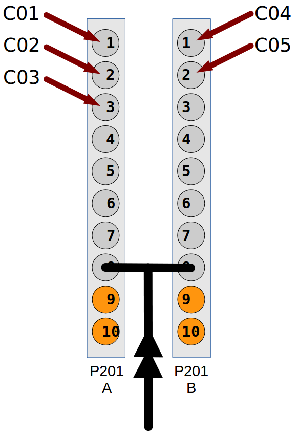
Here is an example how to configure and run two P201 cards:
- syncronized by an external trigger on input channel 8
- both cards in external trigger multi acquisition mode
- 10 acquisition points
- with an exposure time of 0.1s.
- Card A with channels 1, 2 and 3 (counter names: C01, C02 and C03)
- Card B with channels 1 and 2 (counter names: C04 and C05)
First, start two CT2 bliss rpc servers:
$ bliss-ct2-server --port=8909 --address=/dev/ct2_0
INFO 2017-10-30 15:14:57,680 CardInterface(/dev/ct2_0): connecting to /dev/ct2_0
INFO 2017-10-30 15:14:57,684 CT2Server: Serving CT2 on tcp://0.0.0.0:8909...

$ bliss-ct2-server --port=8910 --address=/dev/ct2_1
INFO 2017-10-30 15:16:32,456 CardInterface(/dev/ct2_1): connecting to /dev/ct2_1
INFO 2017-10-30 15:16:32,458 CT2Server: Serving CT2 on tcp://0.0.0.0:8910...
The YAML configuration should look something like this:
plugin: ct2
cards:
- name: p201_A
  class: CT2
  address: tcp://lid312:8909
  external sync:
    input:
      channel: 8
      polarity inverted: false
  counters:
  - address: 1
    counter name: C01
  - address: 2
    counter name: C02
  - address: 3
    counter name: C03

- name: p201_B
  class: CT2
  address: tcp://lid312:8910
  external sync:
    input:
      channel: 8
      polarity inverted: false
  counters:
  - address: 1
    counter name: C04
  - address: 2
    counter name: C05
...a simple demonstration program:
from gevent import sleep, spawn, wait
from gevent.event import Event

from bliss.common.event import dispatcher
from bliss.config.static import get_config
from bliss.controllers.ct2.device import AcqMode, AcqStatus, StatusSignal

config = get_config()

p201_A = config.get('p201_A')
p201_B = config.get('p201_B')

for card in (p201_A, p201_B):
    card.acq_mode = AcqMode.ExtTrigMulti
    card.acq_expo_time = 0.1
    card.acq_point_period = None
    card.acq_nb_points = 10

p201_A.acq_channels = 1, 2, 3
p201_B.acq_channels = 1, 2

finish_A, finish_B = Event(), Event()
def on_state_changed(value, finish=None):
    if value == AcqStatus.Ready:
        finish.set()

dispatcher.connect(functools(on_state_changed, finish=finish_A),
                   sender=p201_A, signal=StatusSignal)
dispatcher.connect(functools(on_state_changed, finish=finish_B),
                   sender=p201_B, signal=StatusSignal)

p201_A.prepare_acq()
p201_B.prepare_acq()
p201_A.start_acq()
p201_B.start_acq()

wait([finish_A, finish_B])
print('Done!')
Master and slave configuration
If the acquisition is triggered by one of the CT2 cards, this card is named the master card and the other card(s) is(are) slave(s). The master card will syncronize all other hardware (other CT2 cards, detectors, multiplexers, etc) via an output gate signal. The slave card(s) will follow this signal by configuring its acquisition mode to external gate.
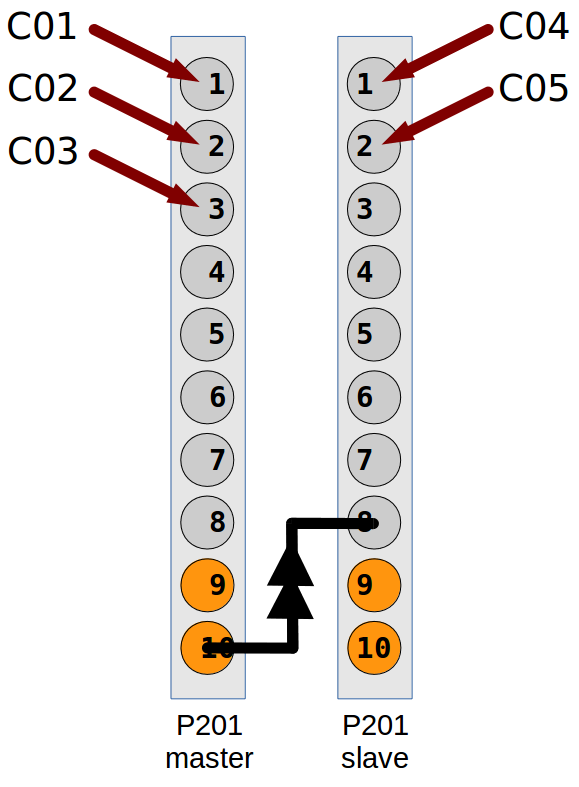
Here is an example how to configure and run two P201 cards:
- Card A is master, with output gate signal channel 10
- Card B is slave, syncronized by an external trigger on input channel 8
- Card A in internal trigger single acquisition mode
- 10 acquisition points
- with an exposure time of 0.1s.
- with a point period of 0.15s
- Card A with channels 1, 2 and 3 (counter names: C01, C02 and C03)
- Card B with channels 1 and 2 (counter names: C04 and C05)
First, start two CT2 bliss rpc servers:
$ bliss-ct2-server --port=8909 --address=/dev/ct2_0
INFO 2017-10-30 15:14:57,680 CardInterface(/dev/ct2_0): connecting to /dev/ct2_0
INFO 2017-10-30 15:14:57,684 CT2Server: Serving CT2 on tcp://0.0.0.0:8909...

$ bliss-ct2-server --port=8910 --address=/dev/ct2_1
INFO 2017-10-30 15:16:32,456 CardInterface(/dev/ct2_1): connecting to /dev/ct2_1
INFO 2017-10-30 15:16:32,458 CT2Server: Serving CT2 on tcp://0.0.0.0:8910...
The YAML configuration should look something like this:
plugin: ct2
cards:
- name: p201_A
  class: CT2
  address: tcp://lid312:8909
  external sync:
    output:
      channel: 10
  counters:
  - address: 1
    counter name: C01
  - address: 2
    counter name: C02
  - address: 3
    counter name: C03

- name: p201_B
  class: CT2
  address: tcp://lid312:8910
  external sync:
    input:
      channel: 8
      polarity inverted: false
  counters:
  - address: 1
    counter name: C04
  - address: 2
    counter name: C05
...a simple demonstration program:
from gevent import sleep, spawn, wait
from gevent.event import Event

from bliss.common.event import dispatcher
from bliss.config.static import get_config
from bliss.controllers.ct2.client import CT2
from bliss.controllers.ct2.device import AcqMode, AcqStatus, StatusSignal

config = get_config()

master = config.get('p201_A')
slave = config.get('p201_B')

master.acq_mode = AcqMode.IntTrigSingle
master.acq_expo_time = 0.1
master.acq_point_period = 0.15
master.acq_nb_points = 10
master.acq_channels = 1, 2, 3

slave.acq_mode = AcqMode.ExtGate
slave.acq_expo_time = None
slave.acq_point_period = None
slave.acq_nb_points = 10
slave.acq_channels = 1, 2

finish_master, finish_slave = Event(), Event()
def on_state_changed(value, finish=None):
    if value == AcqStatus.Ready:
        finish.set()

dispatcher.connect(functools(on_state_changed, finish=finish_master),
                   sender=master, signal=StatusSignal)
dispatcher.connect(functools(on_state_changed, finish=finish_slave),
                   sender=slave, signal=StatusSignal)

master.prepare_acq()
slave.prepare_acq()
master.start_acq()
slave.start_acq()

wait([finish_master, finish_slave])
print('Done!')
Note
you can change the input and output channels at any time in a program by
means of <dev>.input_channel = <channel number> and
<dev>.output_channel = <channel number>, respectively.
Spec & TANGO configuration
Bliss provides a TANGO_ server and a set of spec macros in case you need to control the card through Spec:
First you need to have a running bliss-ct2-server. Check the beginning of
this chapter to find out out to do it.
TANGO configuration
After, you need to configure a CT2 TANGO_ server. In Jive just go to the menu
bar, select Edit --> Create server and type in the following:
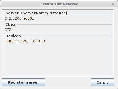
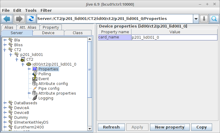
(replace p201_lid001_0 with a name at your choosing)
The final step in configuring the server is to add a property called card_name. Its value should be the name of the object you gave in the YAML_ configuration:
Spec configuration
bliss also provides a ct2.mac macro counter/timer so it can be used from spec. It communicates with the CT2 TANGO device.
Don’t forget to add in setup need bliss/ct2.
Enter config and in the Motor and Counter Device Configuration (Not CAMAC) screen, in the SCALERS list add a new item so it looks like this:
SCALERS        DEVICE                    ADDR  <>MODE  NUM                 <>TYPE
    YES           ct2  id00/ct2/p201_lid001_0           11    Macro Counter/Timer
After, in the Scaler (Counter) Configuration screen, add the counters and/or timer (don’t forget that the Unit is the nth-1 device in the list of Macro Counter or Macro Counter/Timer on the previous screen).
If you add a CT2 timer, the Chan must be 0. The CT2 timer is capable of working in 6 different frequencies: 1.25 KHz, 10 KHz, 125 KHz, 1 MHz, 12.5 MHz and 100 MHz. The spec Scale Factor selects this frequency. The standard working frequency is 1 MHz which correspondes to a Scale Factor of 1E6. Example:
Scaler (Counter) Configuration

Number        Name  Mnemonic  <>Device  Unit  Chan   <>Use As  Scale Factor
     0     Seconds       sec   MAC_CNT     0     0   timebase       1000000
     1      p201_3    p201_3   MAC_CNT     0     3    counter             1
Supported acquisition types
Here is a brief summary of the current acquisition types supported by the CT2.
Point period: The time which corresponds to acquisition of one single point. This period is sub-divided in exposure time and a dead time.
Exposure time: The time during which the input channels are enabled to count
SESSION_SXM [5]: from bliss.controllers.ct2.device import AcqMode as CT2AcqMode
SESSION_SXM [6]: for ii in list(CT2AcqMode):
            ...:     print(ii.value, ii)

0 AcqMode.IntTrigReadout
1 AcqMode.SoftTrigReadout
2 AcqMode.IntTrigSingle
3 AcqMode.IntTrigMulti
4 AcqMode.ExtTrigSingle
5 AcqMode.ExtTrigMulti
6 AcqMode.ExtGate
7 AcqMode.ExtTrigReadout
Internal Trigger Single (2)

Start by software. Trigger by internal clock. Internal clock determines exposure time (constant) and point period (constant).
Note that in this mode, the acquisition finishes after the last point period, where in non single modes it ends right after exposure time ends.
Internal Trigger Multi (3)

Start by software. Hardware takes one single point. Each point is triggered by software. Internal clock determines exposure time (constant).
Internal Trigger Readout (0)

Start by software. Trigger by internal clock which determines exposure time. Trigger ends previous acquisition and starts the next with no dead time.
This mode is similar to Internal Trigger Single when point period equals exposure time (ie, no dead time).
Software Trigger Readout (1)

Start by software; trigger by software. Trigger ends previous acquisition and starts next with no dead time. Exposure time determined by trigger.
External Trigger Single (4)

Start by external trigger. Trigger by internal clock. Internal clock determines exposure time (constant) and point period (constant).
Note that in this mode, the acquisition finishes after the last point period, where in non single modes it ends right after exposure time ends.
This mode is similar to Internal Trigger Single except that the start is done by an external trigger instead of software.
External Trigger Multi (5)

Start by external trigger. Trigger by external trigger. Internal clock determines exposure time (constant).
This mode is similar to Internal Trigger Multi except that the start and the triggers are by an external trigger instead of software start and software trigger.
External gate (6)

Start by external trigger. Exposure time determined by input gate signal.
External Trigger Readout (7)

Start by external trigger. Trigger by external trigger. Trigger ends previous acquisition and starts next with no dead time. Exposure time determined by trigger.
This mode is similar to Internal Trigger Readout except that the start and the triggers are by an external trigger instead of software start and software trigger.